
TM 5-3805-294-23-4
0567
REMOVAL - Continued
7.
Disconnect auxiliary wiring harness SR/H connector (Figure 1, Item 19) from auxiliary wiring harness connector
(Figure 1, Item 20).
8.
Remove nut (Figure 2, Item 21), washer (Figure 2, Item 22), and ground wire (Figure 2, Item 23) from machine
frame (Figure 2, Item 24).
24
21
22
23
HYEX02820
Figure 2. Ground Wire Removal.
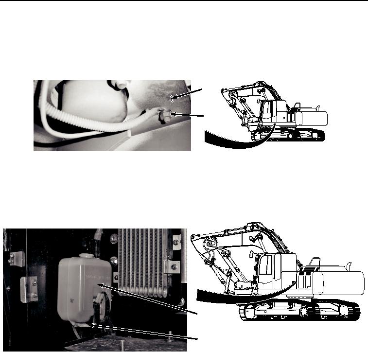
NOTE
Place drain pan under hose being removed.
9.
Disconnect wiper hose (Figure 3, Item 25) from washer reservoir (Figure 3, Item 26).
26
25
HYEX02821
Figure 3.
Wiper Hose Removal.
10.
Cut tie wraps as necessary and tie wiper hose (Figure 3, Item 25) clear of obstructions.
NOTE
Electrical panel needs to be loose so it does not interfere with cab removal. Do not remove.
11.
Remove three bolts (Figure 4, Item 27) and washers (Figure 4, Item 28) from electrical panel (Figure 4, Item
29).