
TM 5-3805-294-23-4
0567
REMOVAL
WARNING
Ensure electrical power is off prior to working on all electrical connections. Prior to working
on or around vehicle, remove all jewelry, such as rings, ID tags, bracelets, etc. Jewelry, and
tools can catch on equipment, contact positive electrical circuits, and cause a direct short,
severe burns, or electrical shock. Failure to comply may result in injury or death to personnel.
NOTE
Some screws used in this task have captive lockwashers permanently attached. If
removed, the replacement screw and lockwasher must be ordered separately.
Tag and mark wires, connectors, and wiring harnesses prior to removal to ensure proper
installation.
Note location and routing of hose prior to removal to ensure proper installation.
Position drain pan under hose being disconnected.
1.
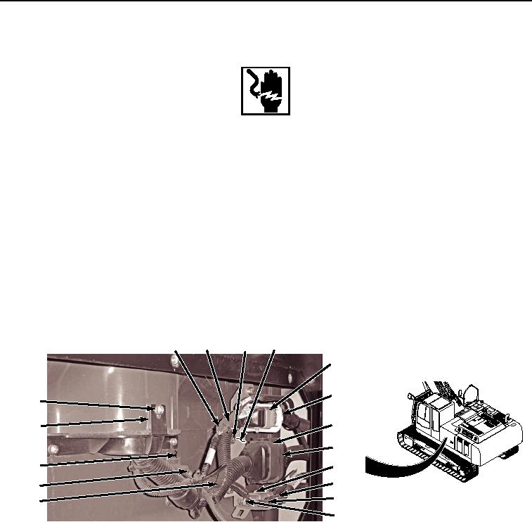
Remove two bolts (Figure 1, Item 1), washers (Figure 1, Item 2), and clamps (Figure 1, Item 3) from cab wiring
harness (Figure 1, Item 4).
19
20
1, 2, 3 12
10
11
5, 6, 7
13
8
14
9
18
16
1, 2, 3
15
4
17
HYEX02819
Figure 1.
Cab Wiring Harness Disconnect.
2.
Remove three screws (Figure 1, Item 5), lockwashers (Figure 1, Item 6), washers (Figure 1, Item 7), and cover
(Figure 1, Item 8) from cab (Figure 1, Item 9). Discard lockwashers.
3.
Disconnect cab wiring harness W1 at connection X4 (Figure 1, Item 10) from machine wiring harness W2
connector (Figure 1, Item 11) and bracket (Figure 1, Item 12).
4.
Disconnect cab wiring harness W1 at connection X3 (Figure 1, Item 13) from machine wiring harness W2
connector (Figure 1, Item 14) and bracket (Figure 1, Item 12).
5.
Disconnect cab wiring harness W1 at connection X41 (Figure 1, Item 15) from machine wiring harness W2
connector (Figure 1, Item 16) and bracket (Figure 1, Item 12).
6.
Disconnect cab wiring harness W1 at connection X42 (Figure 1, Item 17) from machine wiring harness W2
connector (Figure 1, Item 18) and bracket (Figure 1, Item 12).