
TM 5-3805-294-23-4
0567
REMOVAL - Continued
45
42
43
41
4
44
9
43
29
HYEX02826
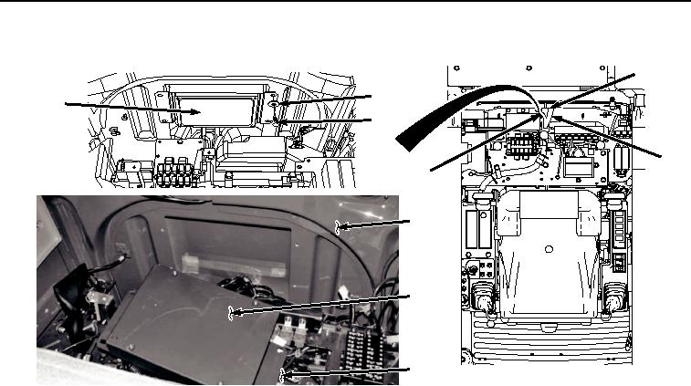
Figure 7.
Main Controller and Cab Wiring Harness Removal.
18.
Move main controller assembly (Figure 7, Item 43) over electrical panel (Figure 7, Item 29) to clear cab (Figure
7, Item 9).
19.
Carefully pass cab wiring harness (Figure 7, Item 4) and auxiliary wiring harness (Figure 7, Item 44) through
cab access (Figure 7, Item 45).
20.
Remove seven screws (Figure 8, Item 46), lockwashers (Figure 8, Item 47), washers (Figure 8, Item 48), and
fresh air filter housing (Figure 8, Item 49) from cab (Figure 8, Item 9). Discard lockwashers.