
TM 5-3805-294-23-4
0567
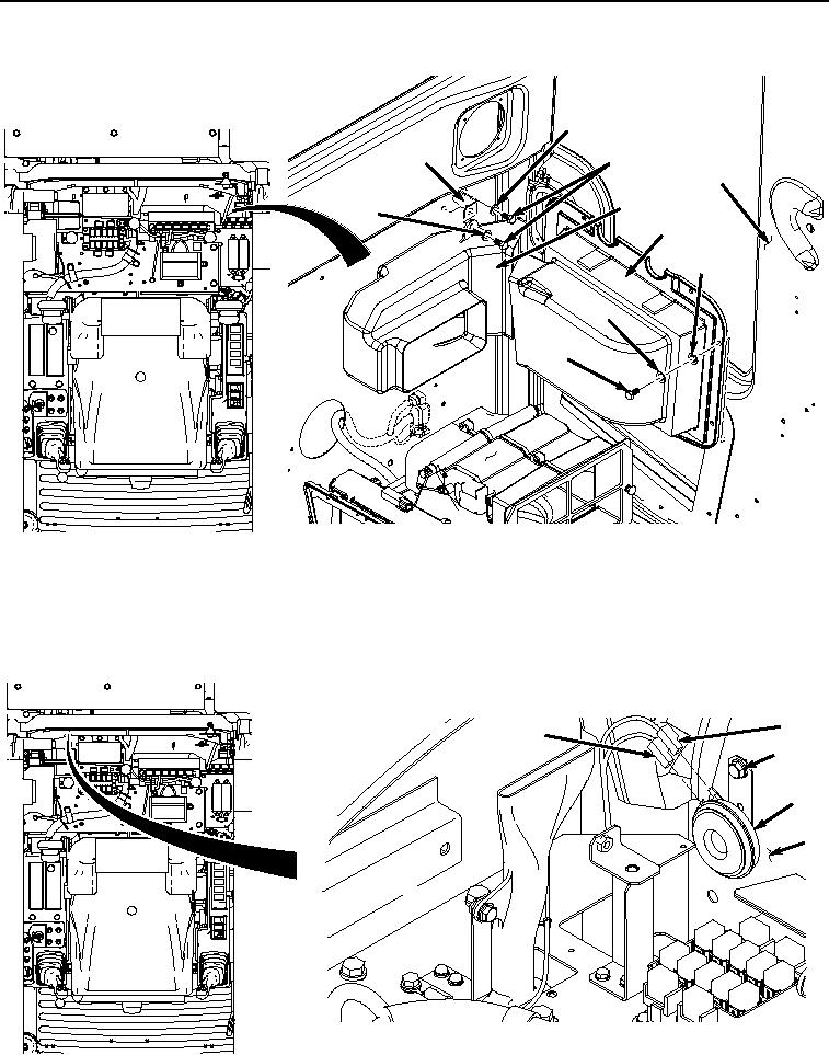
REMOVAL - Continued
51
52
50
9
53
51
49
48
47
46
HYEX02827
Figure 8.
Fresh Air Duct Removal.
21.
Remove two bolts (Figure 8, Item 50), washers (Figure 8, Item 51), bracket (Figure 8, Item 52), and air duct
(Figure 8, Item 53) from cab (Figure 8, Item 9).
22.
Remove connector (Figure 9, Item 54) and connector (Figure 9, Item 55) from alarm (Figure 9, Item 56).
55
54
57, 58
56
9
HYEX02828
Alarm Removal.
Figure 9.