
TM 5-3805-294-23-4
0567
REMOVAL - Continued
88
90, 91
89
89
88
92, 93, 94
9
HYEX02833
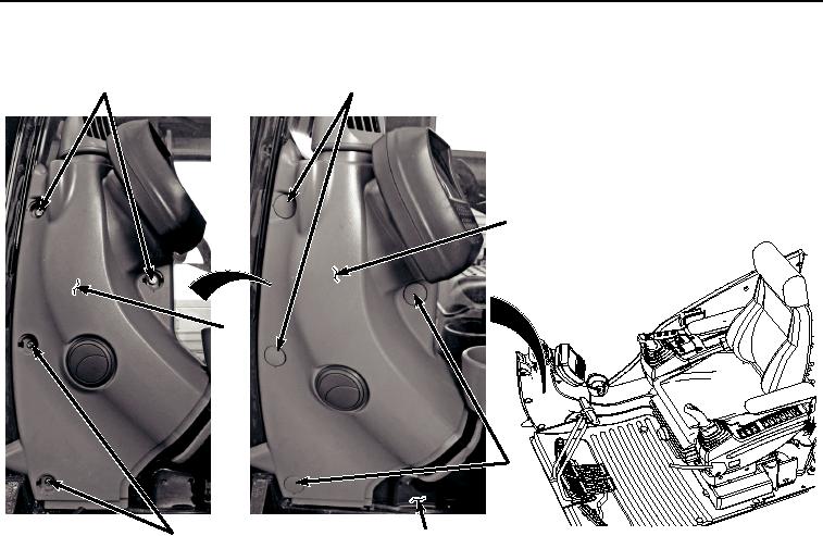
Figure 14.
Console Removal.
37.
Remove two bolts (Figure 14, Item 90) and washers (Figure 14, Item 91) from console (Figure 14, Item 89).
38.
Remove two screws (Figure 14, Item 92), lockwashers (Figure 14, Item 93), washers (Figure 14, Item 94), from
console (Figure 14, Item 89). Discard lockwashers.
39.
Remove console (Figure 14, Item 89) from cab (Figure 14, Item 9).
40.
Remove ash tray (Figure 15, Item 95) from ashtray housing (Figure 15, Item 96).