
TM 5-3805-294-23-4
0567
REMOVAL - Continued
101, 102, 103
100
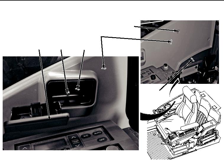
97, 98, 99
95
96
9
HYEX02834
Figure 15.
Ashtray and Cover Removal.
41.
Remove screw (Figure 15, Item 97), lockwasher (Figure 15, Item 98), washer (Figure 15, Item 99), and ashtray
housing (Figure 15, Item 96) from cover (Figure 15, Item 100). Discard lockwasher.
42.
Remove six screws (Figure 15, Item 101), lockwashers (Figure 15, Item 102), washers (Figure 15, Item 103),
and cover (Figure 15, Item 100) from cab (Figure 15, Item 9). Discard lockwashers.
43.
Remove bolt (Figure 16, Item 104), washer (Figure 16, Item 105), and air duct (Figure 16, Item 106) from cab
(Figure 16, Item 9).