
TM 5-3805-294-23-4
0567
REMOVAL - Continued
114
115
121
112
114
122
112
113
121
115
113
123
122
123
116
121
117
122
110
121
122
123
111
116
116
120
117
116
117
119
117
9
116
118
116
117
123
117
HYEX02837
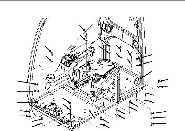
Figure 18. Cab Hardware Removal.
46.
Remove two screws (Figure 18, Item 112) and washers (Figure 18, Item 113) from cab (Figure 18, Item 9).
47.
Remove two screws (Figure 18, Item 114) and washers (Figure 18, Item 115) from cab (Figure 18, Item 9).
48.
Remove six bolts (Figure 18, Item 116) and washers (Figure 18, Item 117) from cab (Figure 18, Item 9).
49.
Remove bolt (Figure 18, Item 118), washer (Figure 18, Item 119), and spacer (Figure 18, Item 120) from under
cab (Figure 18, Item 9).
50.
Remove four locknuts (Figure 18, Item 121) and washers (Figure 18, Item 122) from cab isolators (Figure 18,
Item 123). Discard locknuts.
51.
Install two lift eyes (Figure 19, Item 124) to upper rear mounts of cab (Figure 19, Item 9) with hardware from
rear cab lights.