
TM 5-3805-294-23-4
0567
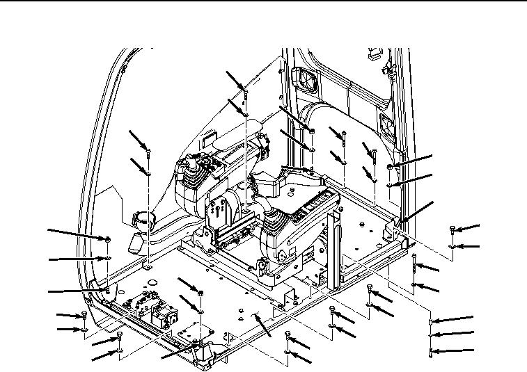
INSTALLATION - Continued
114
115
121
112
114
122
112
113
121
115
113
123
122
123
116
121
117
122
110
121
122
123
111
116
116
120
117
116
117
119
117
9
116
118
116
117
123
117
HYEX02837
Figure 21.
Cab Hardware Installation.
6.
Install bolt (Figure 21, Item 118), washer (Figure 21, Item 119), and spacer (Figure 21, Item 120) to cab (Figure
21, Item 9).
7.
Tighten locknuts (Figure 21, Item 121) to 152 lb-ft (206 Nm).
8.
Tighten bolt (Figure 21, Item 118) to 406 lb-ft (550 Nm).
9.
Install six bolts (Figure 21, Item 116) and washers (Figure 21, Item 117) to cab (Figure 21, Item 9).
10.
Install two screws (Figure 21, Item 114) and washers (Figure 21, Item 115) to cab (Figure 21, Item 9).
11.
Install two screws (Figure 21, Item 112) and washers (Figure 21, Item 113) to cab (Figure 21, Item 9).
12.
Install bolt (Figure 21, Item 110) and washer (Figure 21, Item 111) to cab (Figure 21, Item 9).
13.
Install cab mount (Figure 22, Item 109) to cab (Figure 22, Item 9) with three bolts (Figure 22, Item 107) and
washers (Figure 22, Item 108).