• Home
  • Download PDF
  • Order CD-ROM
  • Order in Print
Figure 25. Console Installation.
Figure 27. Cup Holder Installation.

Maintenance Manual For Hydraulic Excavator Type 1 With Hydraulic Thumb And Quick Latch -4 Page Navigation
  571    572    573    574    575  576  577    578    579    580    581  
img
.
TM 5-3805-294-23-4
0567
INSTALLATION - Continued
83
84
85, 86, 87
HYEX02832
9
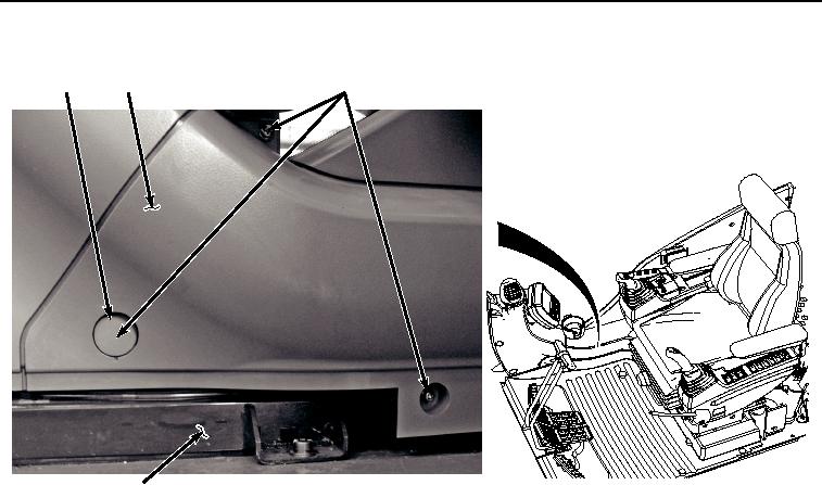
Figure 26. Cover Installation.
23.
Install cap (Figure 26, Item 83) to cover (Figure 26, Item 84).
24.
Install cup holder housing (Figure 27, Item 79) to cab (Figure 27, Item 9) with two screws (Figure 27, Item 80),
lockwashers (Figure 27, Item 81), and washers (Figure 27, Item 82).
0567-24


Privacy Statement
Press Release
Contact

© Copyright Integrated Publishing, Inc.. All Rights Reserved.