
TM 5-3805-294-23-4
0567
INSTALLATION - Continued
37.
Install fresh air filter housing (Figure 31, Item 49) to cab (Figure 31, Item 9) with seven screws (Figure 31, Item
46), lockwashers (Figure 31, Item 47), and washers (Figure 31, Item 48).
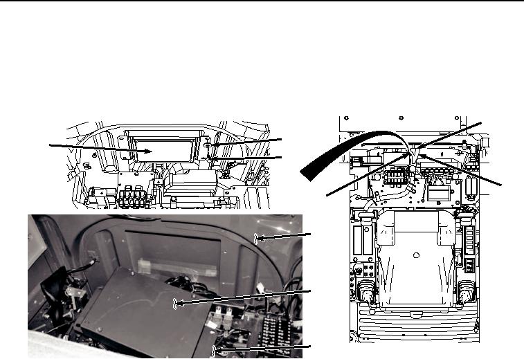
38.
Carefully pass cab wiring harness (Figure 32, Item 4) and auxiliary wiring harness (Figure 32, Item 44) through
cab access (Figure 32, Item 45).
45
42
43
41
4
44
9
43
29
HYEX02826
Figure 32. Main Controller and Cab Wiring Harness Installation.
39.
Lift main controller assembly (Figure 32, Item 43) from electrical panel (Figure 32, Item 29) and position it in
rear of cab (Figure 32, Item 9).
40.
Install main controller assembly (Figure 32, Item 43) to cab (Figure 32, Item 9) with four bolts (Figure 32, Item
41) and washers (Figure 32, Item 42).
41.
Install right side bracket (Figure 33, Item 38) to cab (Figure 33, Item 9) with two bolts (Figure 33, Item 39) and
washers (Figure 33, Item 40).