
TM 5-3805-294-23-4
0567
INSTALLATION - Continued
45.
Install fuse panel (Figure 34, Item 32) to electrical panel (Figure 34, Item 29) and left side bracket (Figure 34,
Item 33) with four bolts (Figure 34, Item 30) and washers (Figure 34, Item 31).
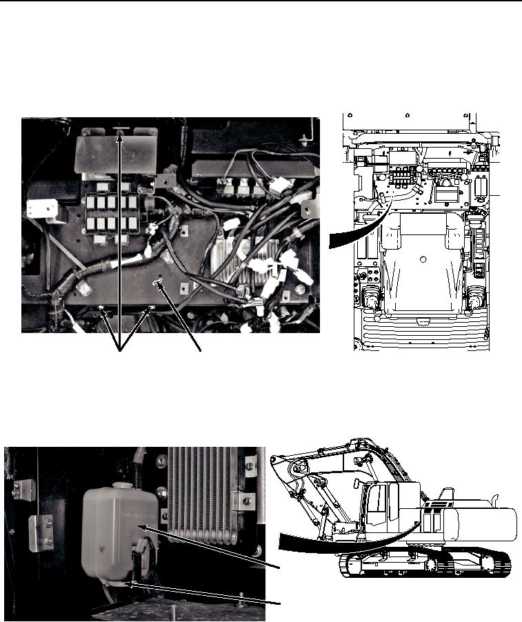
46.
Install three bolts (Figure 35, Item 27) and washers (Figure 35, Item 28) to electrical panel (Figure 35, Item
29).
27, 28
29
HYEX02823
Figure 35.
Electrical Panel Hardware Installation.
47.
Route wiper hose (Figure 36, Item 25) to washer reservoir (Figure 36, Item 26) and install tie wraps as
necessary.
26
25
HYEX02821
Figure 36.
Wiper Hose Installation.
48.
Connect wiper hose (Figure 36, Item 25) to washer reservoir (Figure 36, Item 26).