
TM 5-3805-294-23-4
0567
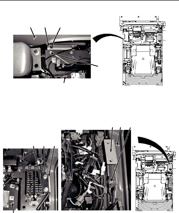
INSTALLATION - Continued
9
38
39, 40
36, 37
29
HYEX02825
Figure 33. Right Side Bracket Installation.
42.
Install electrical panel (Figure 33, Item 29) to right side bracket (Figure 33, Item 38) with two bolts (Figure 33,
Item 36) and washers (Figure 33, Item 37).
43.
Install left side bracket (Figure 34, Item 33) to cab (Figure 34, Item 9) with two bolts (Figure 34, Item 34) and
washers (Figure 34, Item 35).
33
9
34, 35
32
30, 31
33
HYEX02824
29
Figure 34.
Left Side Bracket Installation.
44.
Position fuse panel (Figure 34, Item 32) on electrical panel (Figure 34, Item 29) and left side bracket (Figure
34, Item 33).