
TM 5-3805-294-23-4
0568
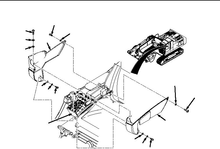
SIDE COVERS REMOVAL - Continued
25
17
26
18
20
19
31
24
23
30
22
21
10
29
28
27
HYEX00855
Figure 2.
Side Covers Removal.
2.
Remove screw (Figure 2, Item 22), lockwasher (Figure 2, Item 23), and washer (Figure 2, Item 24) from cover
(Figure 2, Item 20). Discard lockwasher.
3.
Remove screw (Figure 2, Item 25), washer (Figure 2, Item 26), and cover (Figure 2, Item 20) from right-hand
console (Figure 2, Item 10).
4.
Remove screw (Figure 2, Item 27), lockwasher (Figure 2, Item 28), and washer (Figure 2, Item 29) from cover
(Figure 2, Item 21). Discard lockwasher.
5.
Remove screw (Figure 2, Item 30), washer (Figure 2, Item 31), and cover (Figure 2, Item 21) from right-hand
console (Figure 2, Item 10).
END OF TASK
SIDE COVERS INSTALLATION
1.
Install cover (Figure 3, Item 21) to right-hand console (Figure 3, Item 10) with screw (Figure 3, Item 30) and
washer (Figure 3, Item 31).