
TM 5-3805-294-23-4
0568
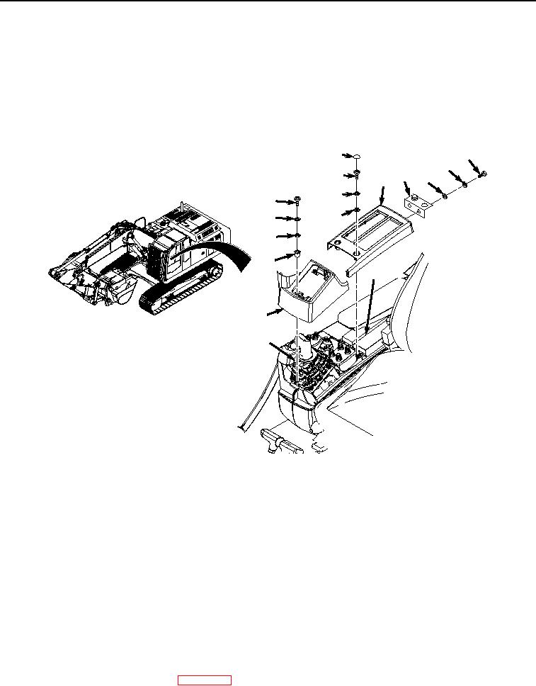
UPPER COVERS INSTALLATION - Continued
tools can catch on equipment, contact positive electrical circuits, and cause a direct short,
severe burns, or electrical shock. Failure to comply may result in injury or death to personnel.
NOTE
Install boot as noted prior to removal.
1.
Install cover (Figure 4, Item 16) to right-hand console (Figure 4, Item 10).
6
1
2
7
4
3
5
8
11
12
9
13
14
10
16
15
HYEX00854
Figure 4.
Upper Cover Installation.
2.
Install four screws (Figure 4, Item 11), lockwashers (Figure 4, Item 12), washers (Figure 4, Item 13), and
spacers (Figure 4, Item 14) to boot (Figure 4, Item 15) and cover (Figure 4, Item 16).
3.
Install cover (Figure 4, Item 5) to right-hand console (Figure 4, Item 10).
4.
Install two screws (Figure 4, Item 7), lockwashers (Figure 4, Item 8), and washers (Figure 4, Item 9) to cover
(Figure 4, Item 5).
5.
Install two caps (Figure 4, Item 6) to cover (Figure 4, Item 5).
6.
Install two screws (Figure 4, Item 1), lockwashers (Figure 4, Item 2), washers (Figure 4, Item 3), and bracket
(Figure 4, Item 4) to cover (Figure 4, Item 5).
END OF TASK
FOLLOW-ON MAINTENANCE
1.
Connect negative battery cable. (WP 0521)