
TM 5-3805-294-23-4
0567
INSTALLATION - Continued
88
90, 91
89
89
88
92, 93, 94
9
HYEX02833
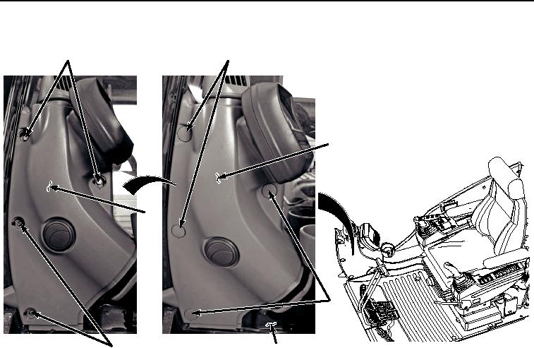
Figure 25. Console Installation.
19.
Install to console (Figure 25, Item 89) to cab (Figure 25, Item 9) with two screws (Figure 25, Item 92),
lockwashers (Figure 25, Item 93), and washers (Figure 25, Item 94).
20.
Install two bolts (Figure 25, Item 90) and washers (Figure 25, Item 91) to console (Figure 25, Item 89).
21.
Install four caps (Figure 25, Item 88) to console (Figure 25, Item 89).
22.
Install cover (Figure 26, Item 84) to cab (Figure 26, Item 9) with three screws (Figure 26, Item 85), lockwashers
(Figure 26, Item 86), and washers (Figure 26, Item 87).