
TM 5-3805-294-23-4
0567
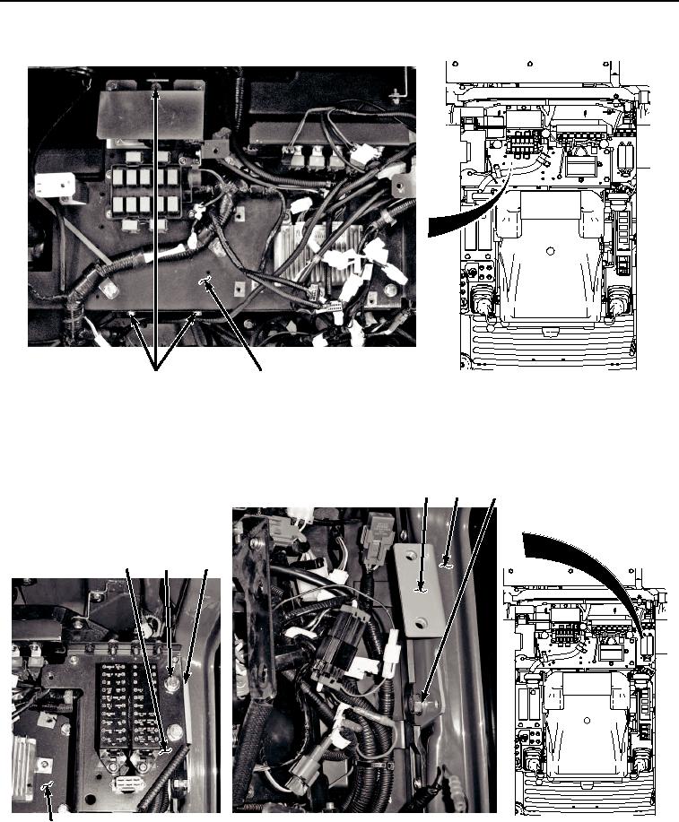
REMOVAL - Continued
27, 28
29
HYEX02823
Figure 4. Electrical Panel Hardware Removal.
12.
Remove four bolts (Figure 5, Item 30), washers (Figure 5, Item 31), and fuse panel (Figure 5, Item 32) from
electrical panel (Figure 5, Item 29) and left side bracket (Figure 5, Item 33).
33
9
34, 35
32
30, 31
33
HYEX02824
29
Figure 5. Left Side Bracket Removal.
13.
Move fuse panel (Figure 5, Item 32) over electrical panel (Figure 5, Item 29) to clear cab (Figure 5, Item 9).