
TM 5-3805-294-23-4
0566
REAR TRAY INSTALLATION - Continued
5.
Install two screws (Figure 12, Item 16) and washers (Figure 12, Item 17) to tray (Figure 12, Item 3).
6.
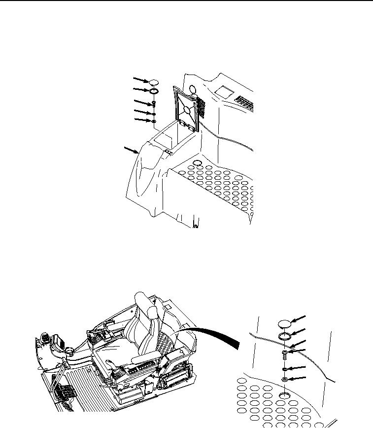
Install screw (Figure 13, Item 9), lockwasher (Figure 13, Item 10), and washer (Figure 13, Item 11) to tray
(Figure 13, Item 3).
7
8
9
10
11
3
HYEX00947
Figure 13. Rear Tray Left Screw Installation.
7.
Install cap (Figure 13, Item 7) and isolator (Figure 13, Item 8) to tray (Figure 13, Item 3).
8.
Install three screws (Figure 14, Item 4), lockwashers (Figure 14, Item 5), and washers (Figure 14, Item 6) to
tray (Figure 14, Item 3).
1
2
3
4
5
6
HYEX00946
Figure 14. Rear Tray Center Screws Installation.
9.
Install three caps (Figure 14, Item 1) and isolators (Figure 14, Item 2) to tray (Figure 14, Item 3).
END OF TASK