
TM 5-3805-294-23-4
0566
REAR TRAY DISASSEMBLY - Continued
2.
Remove mechanical lighter (Figure 4, Item 20), gasket (Figure 4, Item 21), and shell (Figure 4, Item 22) from
tray (Figure 4, Item 3).
END OF TASK
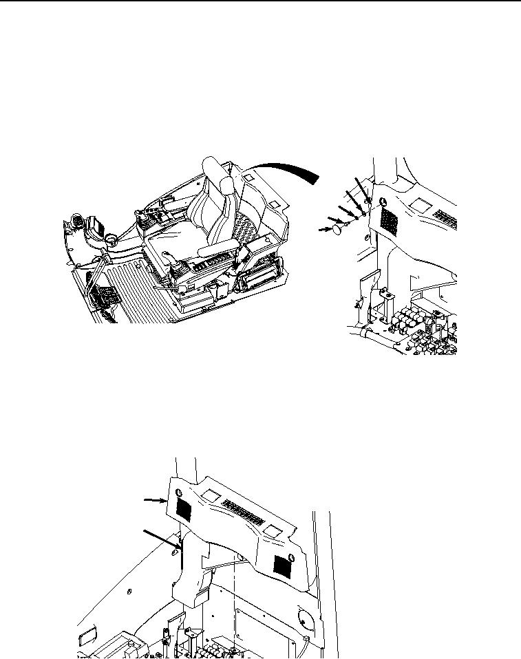
REAR COVER AND AIR CONDITIONER REAR DUCT REMOVAL
1.
Remove two caps (Figure 5, Item 23) from cover (Figure 5, Item 24).
24
27
26
25
23
HYEX00950
Figure 5.
Rear Cover Removal.
2.
Remove two screws (Figure 5, Item 25), lockwashers (Figure 5, Item 26), and washers (Figure 5, Item 27) from
cover (Figure 5, Item 24). Discard lockwashers.
3.
Remove cover (Figure 6, Item 24) and air duct (Figure 6, Item 28) from operator cab,
24
28
HYEX00951
Figure 6. Rear Cover and Air Conditioner Rear Duct Removal.