
TM 5-3805-294-23-4
0565
INSTALLATION - Continued
8
9
10
5
7
6
2
1
3
HYEX01382
4
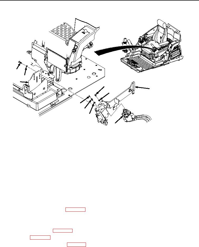
Figure 4.
Left-Hand Console Installation.
2.
Install pilot control valve (Figure 4, Item 4) to console (Figure 4, Item 7) with three bolts (Figure 4, Item 5) and
washers (Figure 4, Item 6).
NOTE
Install bolt and spring pin as noted prior to removal.
3.
Install bolt (Figure 4, Item 1), spring pin (Figure 4, Item 2), and washer (Figure 4, Item 3) to pilot control valve
(Figure 4, Item 4).
END OF TASK
FOLLOW-ON MAINTENANCE
1.
Install pilot shutoff switch. (Volume 5, WP 0756)
2.
Install left-hand console covers. (WP 0564)
3.
Install pilot shutoff lever. (Volume 5, WP 0752)
4.
Install left-hand pilot control grip lever. (Volume 5, WP 0726)
5.
Install left-hand armrest. (WP 0553)
6.
Install seat. (WP 0580)
7.
Connect negative battery cable. (WP 0521)