
TM 5-3805-294-23-4
FIELD MAINTENANCE
ARMRESTS AND BRACKET REPLACEMENT
INITIAL SETUP:
Tools and Special Tools
Equipment Condition
Tool Kit, General Mechanic's: Automotive
Machine safely parked and shut down
(Volume 5, WP 0796, Table 2, Item 119)
(TM 5-3805-294-10). (Volume 5, WP 0794)
Personnel Required
Time to Complete
Construction Equipment Repairer 91L (1)
0.5 Hour(s)
References
TM 5-3805-294-24P: Fig. 118 (Volume 5,
WP 0794)
DA FORM 5988-E or DA FORM 2404 (Volume 5,
WP 0794)
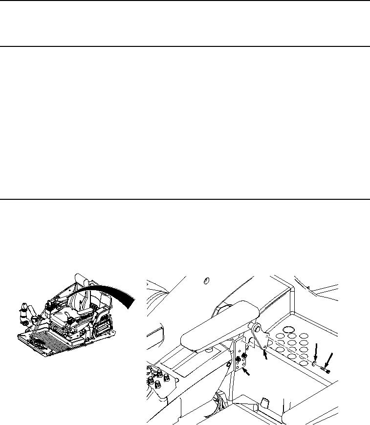
RIGHT-HAND ARMREST REMOVAL
NOTE
Seat shown removed for clarity.
1.
Remove two screws (1), washers (2), and armrest (3) from bracket (4).
2
1
3
4
HYEX00766
Figure 1.
Right-Hand Armrest Removal.
2.
Remove two screws (5), washers (6), and right bracket (4) from right-hand console (7).