
TM 5-3805-294-23-4
0566
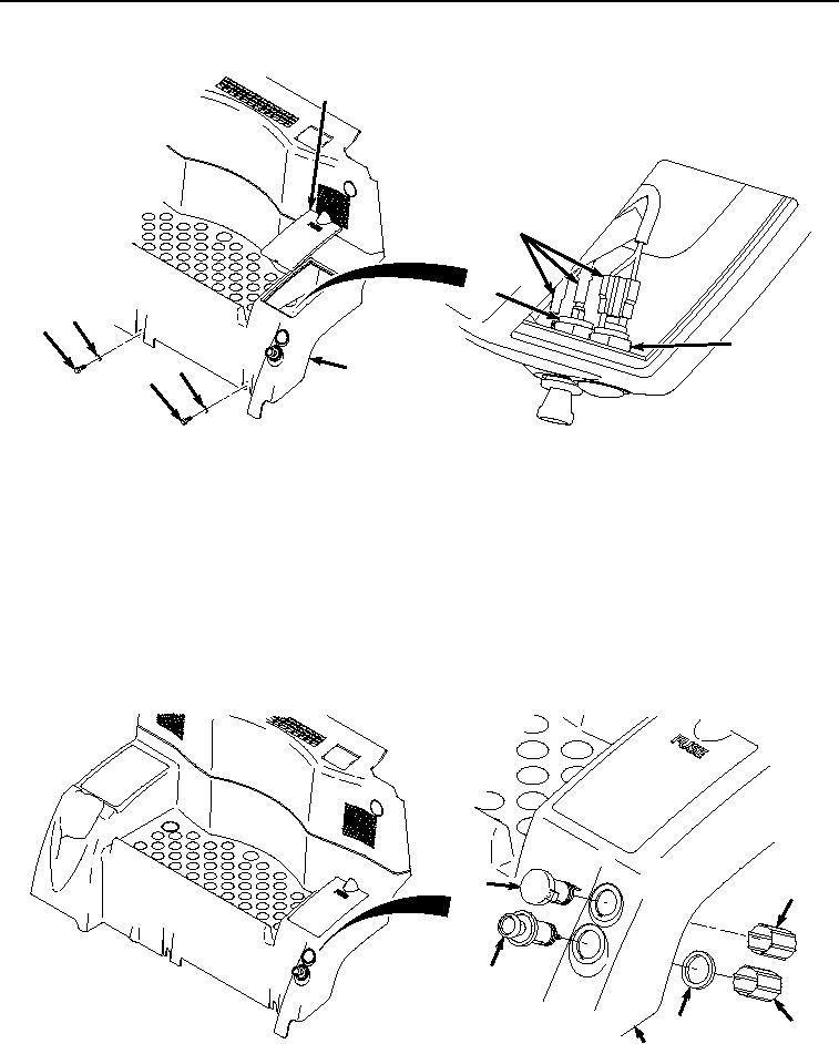
REAR TRAY REMOVAL - Continued
12
13
15
17
16
14
17
3
16
HYEX00948
Figure 3.
Rear Tray Connector Removal.
6.
Remove wiring harness (Figure 3, Item 13) from connector terminal (Figure 3, Item 14) and mechanical lighter
(Figure 3, Item 15).
7.
Remove two screws (Figure 3, Item 16) and washers (Figure 3, Item 17) from tray Figure 3, Item (3).
8.
Remove tray (Figure 3, Item 3) from operator cab.
END OF TASK
REAR TRAY DISASSEMBLY
1.
Remove connector terminal (Figure 4, Item 18) and shell (Figure 4, Item 19) from tray (Figure 4, Item 3).
18
19
20
21
22
3
HYEX00949
Figure 4. Connector Terminal and Mechanical Lighter Removal.