
TM 5-3805-294-23-4
0566
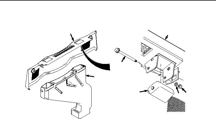
REAR COVER AND AIR CONDITIONER REAR DUCT REMOVAL - Continued
4.
Remove air duct (Figure 7, Item 28) from cover (Figure 7, Item 24).
24
24
31
28
32
30 29
HYEX00952
Figure 7.
Louver Removal.
NOTE
Do not remove louvers unless they require replacement.
Left and right louvers are removed the same way.
5.
Remove nut (Figure 7, Item 29) and washer (Figure 7, Item 30) from one end of shaft (Figure 7, Item 31).
6.
Remove shaft (Figure 7, Item 31) from cover (Figure 7, Item 24).
7.
Remove louver (Figure 7, Item 32) from cover (Figure 7, Item 24).
END OF TASK
REAR COVER AND AIR CONDITIONER REAR DUCT INSTALLATION
NOTE
Left and right louvers are installed the same way.
1.
Install louver (Figure 8, Item 32) to cover (Figure 8, Item 24).