
TM 5-3805-294-23-4
0566
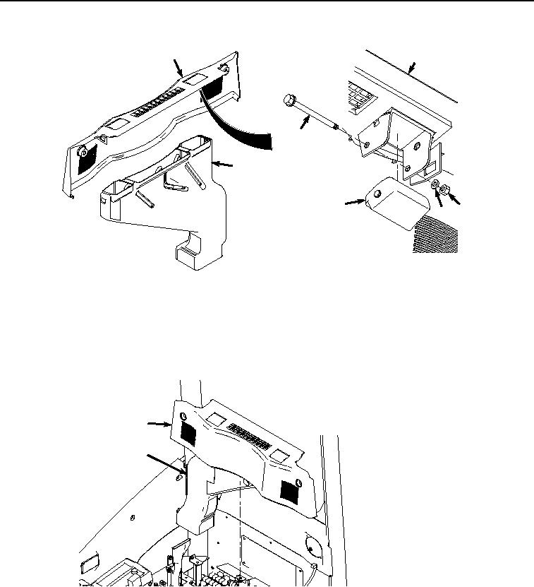
REAR COVER AND AIR CONDITIONER REAR DUCT INSTALLATION - Continued
24
24
31
28
32
30 29
HYEX00952
Figure 8. Louver Installation.
2.
Install shaft (Figure 8, Item 31) to cover (Figure 8, Item 24) with nut (Figure 8, Item 29) and washer (Figure 8,
Item 30).
3.
Install air duct (Figure 8, Item 28) to cover (Figure 8, Item 24).
4.
Install air duct (Figure 9, Item 28) and cover (Figure 9, Item 24) to operator cab.
24
28
HYEX00951
Figure 9.
Rear Cover and Air Conditioner Rear Duct Installation.
5.
Install two screws (Figure 10, Item 25), lockwashers (Figure 10, Item 26), and washers (Figure 10, Item 27) to
cover (Figure 10, Item 24).