
TM 5-3805-294-23-4
0566
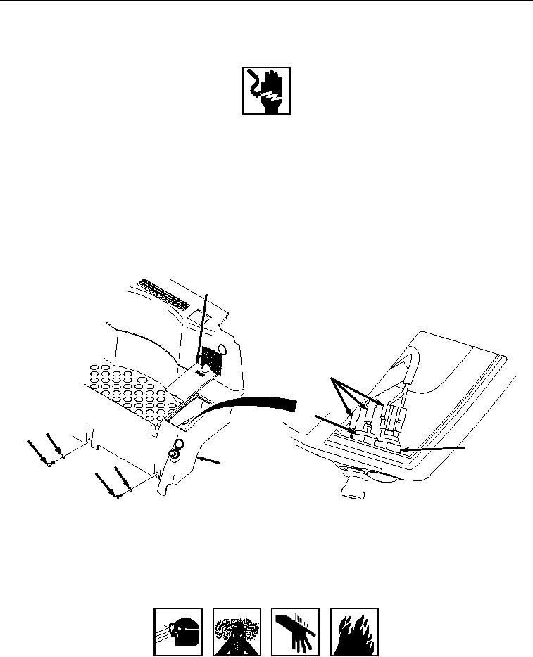
REAR TRAY INSTALLATION
WARNING
Ensure electrical power is off prior to working on all electrical connections. Prior to working
on or around vehicle, remove all jewelry, such as rings, ID tags, bracelets, etc. Jewelry, and
tools can catch on equipment, contact positive electrical circuits, and cause a direct short,
severe burns, or electrical shock. Failure to comply may result in injury or death to personnel.
NOTE
Install wires, connectors, and wiring harnesses as noted prior to removal.
Ensure the wiring harness (13) is pulled up into a position that can be reached through
the fuse access opening after the tray (3) is installed.
1.
Install tray (Figure 12, Item 3) to operator cab.
12
13
15
17
16
14
17
3
16
HYEX00948
Figure 12. Rear Tray Connector Installation.
2.
Install wiring harness (Figure 12, Item 13) to connector terminal (Figure 12, Item 14) and mechanical lighter
(Figure 12, Item 15).
3.
Install cover (Figure 12, Item 12) to tray (Figure 12, Item 3).
WARNING
ADHESIVES AND SEALANTS
4.
Apply thread lock to threads of two screws (Figure 12, Item 16).