
TM 5-3805-294-23-4
0565
ASSEMBLY - Continued
13
14
15
16
17
16
7
11
18
19
12
20
HYEX01383
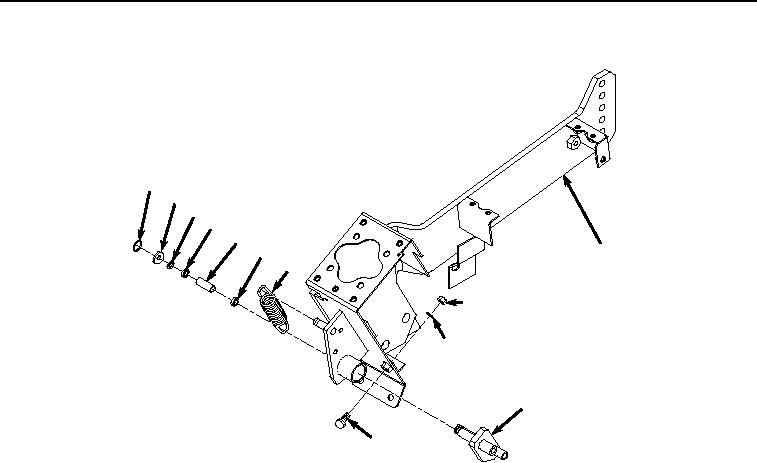
Figure 3. Left-Hand Console Assembly.
2.
Install bracket (Figure 3, Item 12), spacer (Figure 3, Item 17), two bearings (Figure 3, Item 16), shim (Figure
3, Item 15), washer (Figure 3, Item 14), and retaining ring (Figure 3, Item 13) to console (Figure 3, Item 7).
3.
Install spring (Figure 3, Item 11) to bracket (Figure 3, Item 12) and console (Figure 3, Item 7).
END OF TASK
INSTALLATION
1.
Install console (Figure 4, Item 7) to seat stand (Figure 4, Item 10) with three washers (Figure 4, Item 9) and
bolts (Figure 4, Item 8).