
TM 5-3805-294-23-4
0586
INSTALLATION - Continued
14
16
13
15
12
11
5
HYEX01760
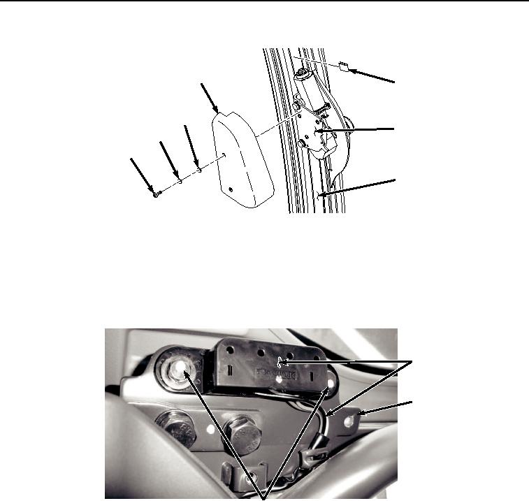
Figure 8. Wiper Motor Cover Installation.
5.
Install cover (Figure 8, Item 14) to windshield wiper motor assembly (Figure 8, Item 15) with two washers
(Figure 8, Item 13), lockwashers (Figure 8, Item 12), and screws (Figure 8, Item 11).
6.
Install windshield wiper motor windshield assembly wiring harness (Figure 9, Item 10) to frame (Figure 9, Item
5) with two washers (Figure 9, Item 9), washers (Figure 9, Item 8), lockwashers (Figure 9, Item 7), and bolts
(Figure 9, Item 6).
10
5
6, 7, 8, 9
HYEX01759
Figure 9. Electrical Connector Installation.
7.
Install cover (Figure 10, Item 4) to frame (Figure 10, Item 5) with two washers (Figure 10, Item 3), lockwashers
(Figure 10, Item 2), and screws (Figure 10, Item 1).