
TM 5-3805-294-23-4
0590
REMOVAL - Continued
3.
With the aid of an assistant, remove four nuts (Figure 2, Item 8), lockwashers (Figure 2, Item 9), washers
(Figure 2, Item 10), and cooling compartment door (Figure 2, Item 7) from frame. Discard lockwashers.
END OF TASK
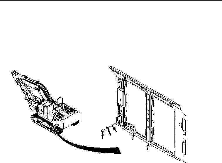
INSTALLATION
1.
Ensure door latch (Figure 3, Item 6) is stowed on cooling compartment door (Figure 3, Item 7).
10
9
8
6
7
HYEX00509
Figure 3.
Cooling Compartment Door Installation.
2.
With the aid of an assistant, position cooling compartment door (Figure 3, Item 7) on frame.
3.
Install cooling compartment door (Figure 3, Item 7) to frame with four washers (Figure 3, Item 10), lockwashers
(Figure 3, Item 9), and nuts (Figure 3, Item 8).
4.
Install coolant heater fuse assembly (Figure 3, Item 3) to relay (Figure 3, Item 4) and frame (Figure 3, Item 5)
with washer (Figure 3, Item 2) and screw (Figure 3, Item 1).