
TM 5-3805-294-23-4
FIELD MAINTENANCE
TRAVEL ALARM CANCEL SWITCH AND WIRING HARNESS REPLACEMENT
INITIAL SETUP:
Equipment Condition (cont.)
Tools and Special Tools
Tool Kit, General Mechanic's: Automotive
Negative battery cable disconnected. (WP 0521)
Left-hand console upper cover removed.
(Volume 5, WP 0796, Table 2, Item 119)
Materials/Parts
Tags (Volume 5, WP 0797, Table 1, Item 52)
Time to Complete
0.6 Hour(s)
Tie Wraps (Volume 5, WP 0797, Table 1, Item
56)
Personnel Required
Construction Equipment Repairer 91L (1)
References
TM 5-3805-294-24P: Fig. 144 (Volume 5,
WP 0794)
DA FORM 5988-E or DA FORM 2404 (Volume 5,
WP 0794)
Equipment Condition
Machine safely parked and shut down
(TM 5-3805-294-10). (Volume 5, WP 0794)
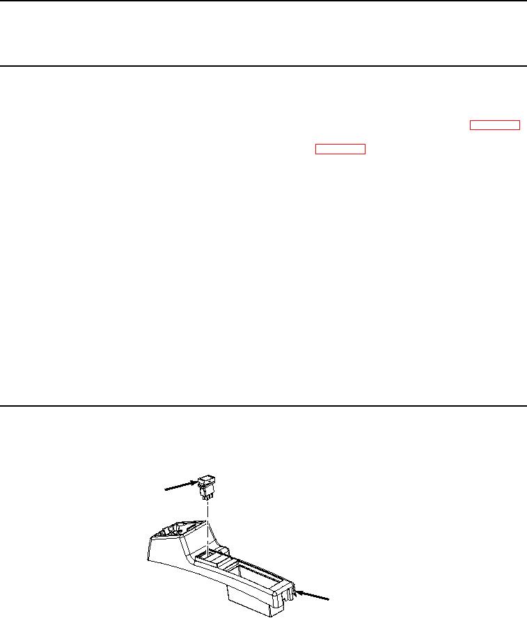
SWITCH REMOVAL
Remove switch (Figure 1, Item 1) from console cover (Figure 1, Item 2).
1
2
HYEX00887
Figure 1. Switch Removal.
END OF TASK