
TM 5-3805-294-23-4
0617
WIRING HARNESS INSTALLATION - Continued
4
3
HYEX00888
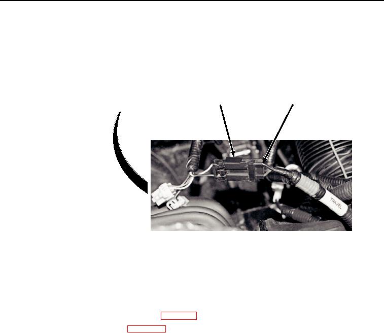
Figure 4. Wiring Harness Installation.
2.
Connect wiring harness (Figure 4, Item 3) to cab wiring harness connector S13 (Figure 4, Item 4).
END OF TASK
FOLLOW-ON MAINTENANCE
1.
Install cab left-hand console upper cover. (WP 0564)
2.
Connect negative battery cable. (WP 0521)
3.
Perform the Standard Follow-On Maintenance Instructions. (Volume 3, WP 0384)
END OF TASK
END OF WORK PACKAGE