
TM 5-3805-294-23-4
0651
REMOVAL - Continued
20
10
11
10
12
11
24
12
10
16
11
22
12
10
11
16
18
25
2
17
13
14
12
19
15
21
16
23
2
HYEX00576
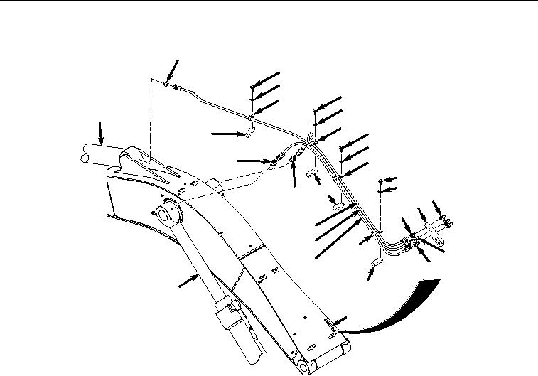
Figure 2. Upper Lines Removal.
7.
Remove line (Figure 2, Item 13) from fitting (Figure 2, Item 17) and fitting (Figure 2, Item 18).
8.
Remove line (Figure 2, Item 14) from fitting (Figure 2, Item 19) and fitting (Figure 2, Item 20).
9.
Remove line (Figure 2, Item 15) from fitting (Figure 2, Item 21) and fitting (Figure 2, Item 22).
10.
Remove three fittings (Figure 2, Item 17), (Figure 2, Item 19), and (Figure 2, Item 21) from boom weldment
(Figure 2, Item 2).
11.
Remove two fittings (Figure 2, Item 18) and (Figure 2, Item 22) from boom cylinders (Figure 2, Item 23).
12.
Remove fitting (Figure 2, Item 20) from arm cylinder (Figure 2, Item 24).
13.
Remove three fittings (Figure 2, Item 25) from boom weldment (Figure 2, Item 2).
END OF TASK