
TM 5-3805-294-23-4
0651
INSTALLATION - Continued
8.
Install lines (Figure 3, Item 13), (Figure 3, Item 14), and (Figure 3, Item 15) to four weldments (Figure 3, Item
16) with four cushion clamps (Figure 3, Item 12), bolts (Figure 3, Item 10), and washers (Figure 3, Item 11).
9.
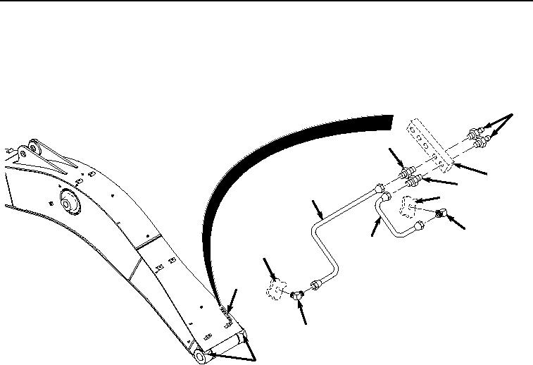
Install two fittings (Figure 4, Item 5) and (Figure 4, Item 8) to boom (Figure 4, Item 9).
1
7
2
4
6
9
5
3
9
2
8
9
HYEX00588
Figure 4.
Lower Lines Installation.
10.
Install two fittings (Figure 4, Item 4) and (Figure 4, Item 7) to boom weldment (Figure 4, Item 2).
11.
Install line (Figure 4, Item 6) to fittings (Figure 4, Item 7) and (Figure 4, Item 8).
12.
Install line (Figure 4, Item 3) to fittings (Figure 4, Item 4) and (Figure 4, Item 5).
13.
Install two fittings (Figure 4, Item 1) to boom weldment (Figure 4, Item 2).
14.
Service lubrication system in accordance with the Lubrication Order (LO 5-3805-294-13).
END OF TASK
FOLLOW-ON MAINTENANCE
Perform the Standard Follow-On Maintenance Instructions. (Volume 3, WP 0384)
END OF TASK
END OF WORK PACKAGE