
TM 5-3805-294-23-4
0651
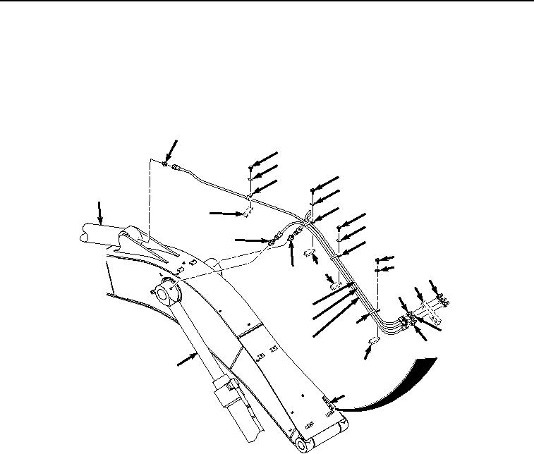
INSTALLATION
NOTE
Install hoses and fittings as noted prior to removal.
Install tie wraps as required.
1.
Install three fittings (Figure 3, Item 25) to boom weldment (Figure 3, Item 2).
20
10
11
10
12
11
24
12
10
16
11
22
12
10
11
16
18
25
2
17
13
14
12
19
15
21
16
23
2
HYEX00576
Figure 3. Upper Lines Installation.
2.
Install fitting (Figure 3, Item 20) to arm cylinder (Figure 3, Item 24).
3.
Install two fittings (Figure 3, Item 18) and (Figure 3, Item 22) to boom cylinders (Figure 3, Item 23).
4.
Install three fittings (Figure 3, Item 17), (Figure 3, Item 19), and (Figure 3, Item 21) to boom weldment (Figure
3, Item 2).
5.
Install line (Figure 3, Item 15) to fitting (Figure 3, Item 21) and fitting (Figure 3, Item 22).
6.
Install line (Figure 3, Item 14) to fitting (Figure 3, Item 19) and fitting (Figure 3, Item 20).
7.
Install line (Figure 3, Item 13) to fitting (Figure 3, Item 17) and fitting (Figure 3, Item 18).