
TM 5-2420-230-24-1
c. Adjustment.
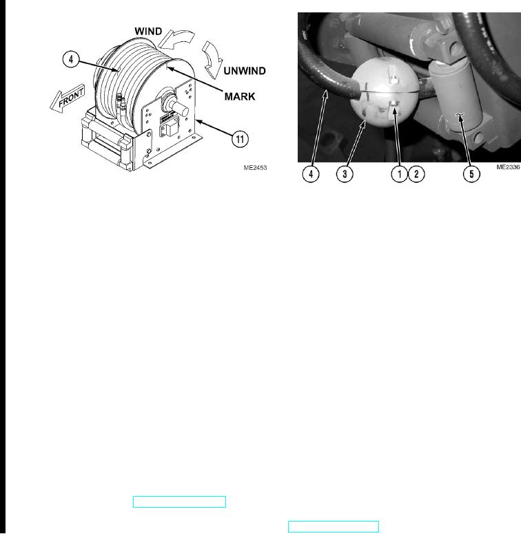
(1)
Mark hose reel (11).
(2)
Using mark, wind hose assembly (4) onto hose reel (11), counting number of turns required to completely stow
hose assembly. Record number of turns counted as value A.
NOTE
Total number of turns available on hose reel is 14.
(3)
Subtract value A from 14. Record difference as value B.
(4)
While retaining hose assembly (4) on hose reel (11), unwind spool a number of turns equal to value B.
NOTE
When hose stop is at rest on hose reel rollers, pawl should not be engaged.
Ensure hose stop is positioned approximately 16 in. (400 mm) from end of hose assembly.
(5)
Pull hose assembly (4) through hose roller (5) and install hose stop (3) on hoses (4) and (5) with two screws (2)
and nuts (1).
d. Follow-On Maintenance.
(1)
Stow hose reel (TM 5-2420-230-10).
(2)
Remove "Do Not Operate" tag from ignition switch (TM 5-2420-230-10).
END OF TASK
Change 1