TM 5-2420-230-24-1
b. Installation.
NOTE
Rise/fall bridge is set to "rising" alarm position when bridge is on two pins closest to wire connectors
and is set to "falling" alarm position when bridge is on two pins farthest to wire connectors. "Falling"
alarm setting is shown.
(1)
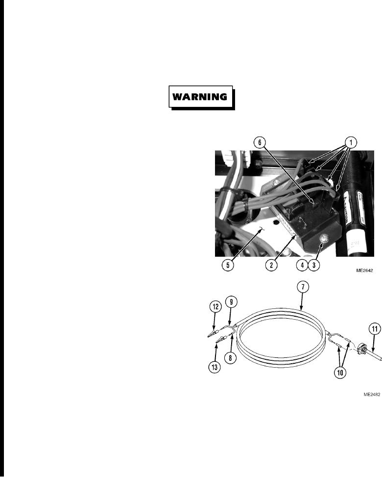
Position rise/fall bridge (6) to proper setting for alarm. HIGH WATER ALARM module should be set to "rising"
position. LOW OIL, LOW FUEL, and LOW WATER ALARM modules should be set to "falling" position.
Remove all jewelry such as rings, dog tags, bracelets, etc. If jewelry or tools contact positive electrical
circuits, a direct short may result. Damage to equipment and injury or death to personnel may occur.
NOTE
Ensure all wires are reconnected to
positions noted prior to removal.
Install cable ties as necessary.
(2)
Install module (2) on power resistor
board (5) with two washers (4) and
screws (3).
(3)
Install wire connectors (1) on module (2).
(4)
Adjust module (2) per Steps c or d.
c. HIGH WATER TEMP ALARM and LOW OIL
PRESSURE ALARM Module Adjustment.
NOTE
After installing the HIGH WATER TEMP
ALARM and LOW OIL PRESSURE
ALARM, an adjustment is necessary. Both
modules are adjusted in a similar manner.
(1)
If required, assemble variable resistor tool.
(a)
Cut a 10 ft. (3 m) length of 18-gage
power cable (7).
(b)
Strip both ends of wires (8) and (9),
leaving 0.25 in (6 mm) of bare wire.
(c)
Cut two 2-in. (50 mm) strips of shrink
tubing (10), placing one on each end of
wires (8) and (9).
(d)
Connect wire (8) to positive (+) side of variable resistor (11).
(e)
Connect wire (9) to negative (-) side of variable resistor (11).
(f)
Slide shrink tubing (10) over connections of wires (8) and (9) variable resistor (11). Install tubing.
(g)
Connect ground clip (12) to wire (9).
(h)
Connect power clip (13) to wire (8).
Change 1
12-28

