
TM 5-2420-230-24-1
b. Installation.
Remove all jewelry such as rings, dog tags, bracelets, etc. If jewelry or tools contact positive electrical
circuits, a direct short may result. Damage to equipment and injury or death to personnel may occur.
NOTE
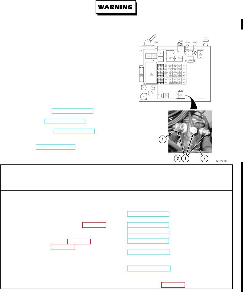
Ensure all wires are reconnected to positions
noted prior to removal.
Install cable ties as necessary.
(1)
Install starter solenoid (3) with two bolts (4).
(2)
Install four wires (2) and nuts (1) to starter
solenoid (3).
c. Follow-On Maintenance.
(1)
Close PDP door (TM 5-2420-230-10).
(2)
Start engine (TM 5-2420-230-10).
(3)
Shut OFF engine (TM 5-2420-230-10).
(4)
Remove "Do Not Operate" tag from ignition
switch (TM 5-2420-230-10).
END OF TASK
12-16.1. AUXILIARY DEFROSTER SWITCH REPLACEMENT.
This Task Covers:
a. Removal
b. Installation
c. Follow-On Maintenance
INITIAL SETUP
Test Equipment
Equipment Conditions
None
TM or Para
Condition Description
Vehicle positioned on level
ground.
Tools and Special Tools
Parking brake applied.
Tool kit, general mechanics, Item 38, Appendix B
Engine shut OFF.
Electrical master switch OFF.
Materials/Parts
"Do Not Operate" tag attached
Tags, identification, Item 63, Appendix C
to ignition switch.
Ties, cable, Item 68, Appendix C
PDP door opened.
Personnel Required
Drawings Required
MOS 62B, Construction Equipment Repairer
TM 5-2420-230-24P Figure 48
References
Estimated Time to Complete Task
None
Refer to MAC in Appendix B
Change 1