
TM 5-2420-230-24-1
(1)
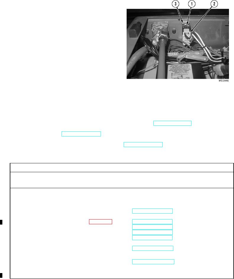
Access rear of rocker switch (1).
(2)
Remove electrical connector (2) from rocker
switch (1).
(3)
Squeeze clips (3) and push up on bottom of
rocker switch (1).
b. Installation.
NOTE
Ensure all wires are reconnected to
positions noted prior to removal.
Install cable ties as necessary.
(1)
Install rocker switch (1). Ensure clips (3)
snap into place.
(2)
Ensure pins are aligned and install electrical connector (2) on rocker switch (1).
c. Follow-On Maintenance.
(1)
Start engine and functionally test rocker switch for proper operation (TM 5-2420-230-10).
(2)
Shut OFF engine (TM 5-2420-230-10).
(3)
Remove "Do Not Operate" tag from ignition switch (TM 5-2420-230-10).
END OF TASK
12-15. RELAY REPLACEMENT.
This Task Covers:
a. Removal
b. Installation
c. Follow-On Maintenance
INITIAL SETUP
Test Equipment
Equipment Conditions
None
TM or Para
Condition Description
Vehicle positioned on level
ground.
Tools and Special Tools
Tool kit, general mechanics, Item 38, Appendix B
Parking brake applied.
Engine shut OFF.
Electrical master switch OFF.
Materials/Parts
None
"Do Not Operate" tag attached
to ignition switch.
PDP door opened.
Personnel Required
MOS 62B, Construction Equipment Repairer
Drawings Required
TM 5-2420-230-24P Figure 48
References
FO-1, Power Distribution Panel layout
Estimated Time to Complete Task
FO-2, Power Distribution Panel schematic
Approximately 0.5 hr.
Change 1