
TM 5-2420-230-24-1
12-16.2. ALARM MODULE REPLACEMENT.
This Task Covers:
a. Removal
b. Installation
c. Adjustment
d. Adjustment
e. Follow-On Maintenance
INITIAL SETUP
Test Equipment
Equipment Conditions
None
TM or Para
Condition Description
Vehicle positioned on level
Tools and Special Tools
ground.
Resistor tool, variable, Item 32.1, Appendix B
Parking brake applied.
Tool kit, electric, Item 37, Appendix B
Engine shut OFF.
Tool kit, general mechanics, Item 38, Appendix B
Electrical master switch OFF.
Materials/Parts
"Do Not Operate" tag attached
Tags, identification, Item 63, Appendix C
to ignition switch.
Ties, cable, Item 68, Appendix C
PDP door open.
Personnel Required
Drawings Required
MOS 62B, Construction Equipment Repairer
TM 5-2420-230-24P Figure 48
TM 5-2420-230-24P Figure 208
References
F01
Estimated Time to Complete Task
Refer to MAC in Appendix B
a. Removal.
Remove all jewelry such as rings, dog tags, bracelets, etc. If jewelry or tools contact positive electrical
circuits, a direct short may result. Damage to equipment and injury or death to personnel may occur.
NOTE
Tag all wires and note their positions
before removal.
Remove cable ties as necessary.
Ensure all wires and plugs are
disconnected and clear before removal.
All alarm modules are removed in the
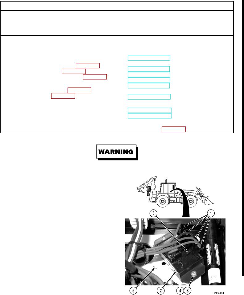
same manner. Low Fuel Alarm is shown.
(1)
Remove wire connectors (1) from
module (2).
(2)
Remove two screws (3), washers (4), and
module (2) from power resistor board (5).
Change 1