
TM 5-2420-230-24-1
NOTE
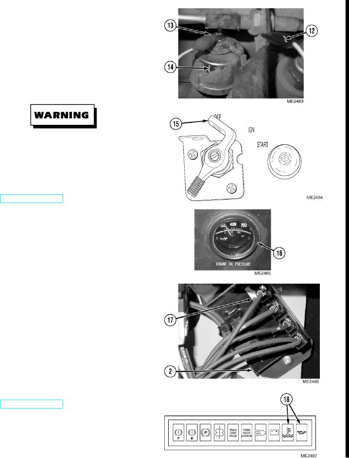
The adjustment to the alarm modules for the
engine oil pressure and engine coolant
temperature gauges are performed in a
simular manner. Engine oil pressure gauge
and sending unit is shown.
(2)
Connect power clip (13) to sending unit (14),
and ground clip (12) to a good ground on
vehicle.
Remove all jewelry such as rings, dog tags,
bracelets, etc. If jewelry or tools contact
positive electrical circuits, a direct short may
result. Damage to equipment and injury or
death to personnel may occur.
(3)
Turn electrical master switch ON
(4)
Turn ignition switch (15) to IGN position.
(5)
Using variable resistor tool, set needle on
gauge (16) to proper position for alarm to
come on. ENGINE COOLANT
TEMPERATURE gauge should be set at
210 F (99 C). ENGINE OIL PRESSURE
gauge should be set at 30 psi (207 kPa).
NOTE
There will be a metallic click when the
module activates the indicator light.
(6)
Turn set screw (17) on module (2) until
appropriate indicator light (18) comes on.
Turn variable resistor (11) to move needle on
gauge (16). Indicator should come on when
gauge reading is outside of normal range,
and go out when gauge is in normal range.
(7)
Turn OFF ignition switch (15).
(8)
Turn electrical master switch OFF
(9)
Remove positive clip (13) from sending
unit (14) and remove ground clip (12) from
vehicle.
Change 1
12-29