
TM 5-2420-230-24-1
a. Removal.
Remove all jewelry such as rings, dog tags,
bracelets, etc. If jewelry or tools contact
positive electrical circuits, a direct short may
result. Damage to equipment and injury or
death to person may occur.
NOTE
Tag all wires and note their positions before
removal.
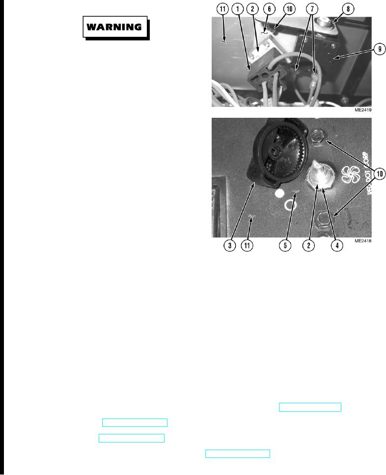
Remove cable ties as necessary.
(1)
Remove wire harness (1) from switch (2).
(2)
Remove knob (3) from switch (2).
(3)
Remove nut (4), plate (5), and switch (2) from
bracket (6).
(4)
If required, remove two wires (7), nut (8), and
circuit breaker (9) from bracket (6).
(5)
If required, remove two screws (10) and
bracket (6) from PDP (11).
b. Installation.
NOTE
Ensure all wires are reconnected to positions noted prior to removal.
Install cable ties as necessary.
(1)
If removed, install bracket (6) on PDP (11) with two screws (10).
(2)
If removed, install circuit breaker (9) on bracket (6) with nut (8) and two wires (7).
(3)
Position switch (2) in bracket (6).
(4)
Install plate (5) and nut (4) on switch (2).
(5)
Install knob (3) on switch (2).
c. Follow On Maintenance.
(1)
Start engine and operate defroster switch to ensure it is functioning properly (TM 5-2420-230-10).
(2)
Shut OFF engine (TM 5-2420-230-10).
(3)
Close PDP door (TM 5-2420-230-10).
(4)
Remove "Do Not Operate" tag from ignition switch (TM 5-2420-230-10).
END OF TASK
Change 1
12-26