
TM 5-2420-230-24-1
a. Removal.
Remove all jewelry such as rings, dog tags, bracelets, etc. If jewelry or tools contact positive electrical
circuits, a direct short may result. Damage to equipment and injury or death to personnel may occur.
NOTE
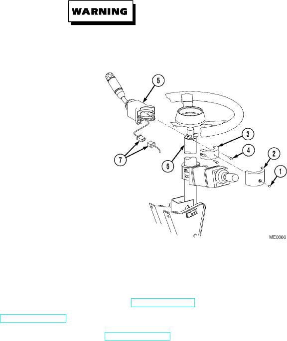
Remove cable ties as necessary.
(1)
Remove screw (1) and mounting clamp
cover (2) from mounting clamp (3).
(2)
Remove screws (4), mounting clamp (3), and
indicator arm (5) from steering column (6).
(3)
Disconnect wiring harness (7) from indicator
arm (5).
b. Installation.
NOTE
Install cable ties as necessary.
(1)
Connect wiring harness (7) to indicator
arm (5).
(2)
Install indicator arm (5), mounting
clamp (3), and screws (4) on steering
column (6).
(3)
Install mounting clamp cover (2) and screw (1) on mounting clamp (3).
c. Follow-On Maintenance.
(1)
Start engine and check for proper operation of indicator arm (TM 5-2420-230-10).
(2)
Shut OFF engine (TM 5-2420-230-10).
(3)
Remove "Do Not Operate" tag from ignition switch (TM 5-2420-230-10).
END OF TASK
Change 1
12-47