
TM 5-2420-230-24-1
b. Installation.
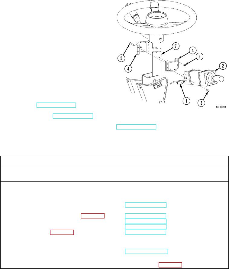
NOTE
Install cable ties as necessary.
(1)
If required, align mounting clamp (4) with
locator pin. Secure mounting clamp on
steering column (7) with screws (5) and new
self-locking nuts (6).
(2)
Install EGS (2) and screws (3) on mounting
clamp (4).
(3)
Connect wiring harness (1) to EGS (2).
c. Follow-On Maintenance.
(1)
Start engine and check for proper operation
of EGS (TM 5-2420-230-10).
(2)
Shut OFF engine (TM 5-2420-230-10).
(3)
Remove "Do Not Operate" tag from ignition switch (TM 5-2420-230-10).
END OF TASK
12-26. INDICATOR ARM REPLACEMENT.
This Task Covers:
a. Removal
b. Installation
c. Follow-On Maintenance
INITIAL SETUP
Test Equipment
Equipment Conditions
None
TM or Para
Condition Description
Vehicle positioned on level
ground.
Tools and Special Tools
Tool kit, general mechanics, Item 38, Appendix B
Parking brake applied.
Engine shut OFF.
Electrical master switch OFF.
Materials/Parts
Ties, cable, Item 68, Appendix C
"Do Not Operate" tag attached
to ignition switch.
Personnel Required
Drawings Required
MOS 62B, Construction Equipment Repairer
TM 5-2420-230-24P Figure 70
References
Estimated Time to Complete Task
None
Refer to MAC in Appendix B
Change 1