
TM 5-2420-230-24-1
Spicer Speciality Axle Division - Technical Publications
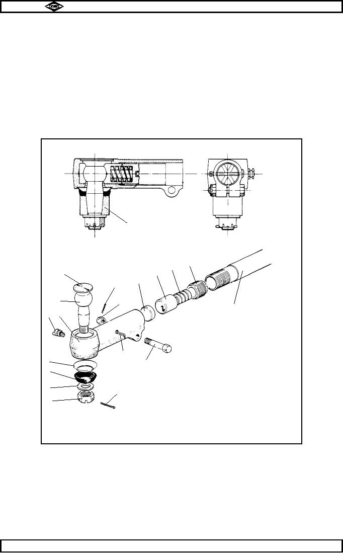
SECTION 22
ASSEMBLY OF BALL SOCKET AND TIE ROD
Fig. No.29
22.1
Using a scraping tool, clean peened areas on ball socket body to enable cover plate (9) to be fitted.
22.2
Knock rubbing pad (14) into its recess in ball socket body.
22.3
Thoroughly grease rubbing pad (14) and ball pin (8) with Shell Retinax LX or equivalent.
22.4
Insert ball pin (8) into body.
22.5
Insert thrust cap (15), compression spring (16) and adjuster piece (17) into body.
Using a suitable tool ie: a 1" x 1/8 " x 9" long flat bar, tighten adjuster piece (17) fully home (SOLID)
22.6
locating thrust cup (15) onto ball pin (8).
TP48
●
Steering lever
17
16
9
●
15
14
10
●
●
●
8
11
●
●
Tie rod
●
6
7
●
●
●
●
●
12
5
13
●
4
3
●
1
2
●
Straight ball socket arrangement
Fig No. 29
Manual No. 1785 Issue A
Page No.B26
Spicer Speciality Axle Division
J-56