
TM 5-3805-294-23-1
0003
HYEX THEORY OF OPERATION - Continued
Engine Operation - Continued
26
25
27
24
28
HYEX01677
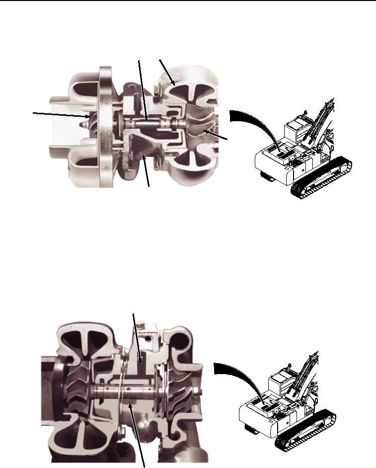
Figure 3. Turbocharger Operation.
Engine oil under pressure from the engine lubrication system is forced through passages in the center housing
(Figure 3, Item 28) to the bearings and directed to the bearings, thrust plate, and thrust sleeve. Oil is sealed from
the compressor and turbine by a piston ring at both ends of the bearing housing.
The turbocharger contains two floating bearings. These bearings have clearance between the bearing OD and the
housing bore as well as clearance between the bearing ID and the shaft OD. These clearances are lubricated by
the oil supply pressure oil (Figure 4, Item 29) and the bearings are protected by a cushion of oil. Discharge oil (Figure
4, Item 30) drains by gravity from the bearing housing to the engine crankcase.
29
30
HYEX01678
Turbocharger Lubrication.
Figure 4.