
TM 5-3805-294-23-1
0003
HYEX THEORY OF OPERATION - Continued
Engine Electronic Control System - Continued
The ECU uses fuel temperature sensor input to calculate fuel density and adjust fuel delivery accordingly. The ECU
also uses the fuel temperature sensor for engine protection purposes. In addition, the glow plug operation is governed
by the fuel temperature. If the temperature of the fuel drops below specification, the glow plug will turn on for a
predetermined length of time.
The ECU uses the intake manifold air temperature (MAT) sensor to measure the temperature of the air in the intake
manifold. The ECU also uses this sensor for engine protection purposes. The MAT sensor is located on the air intake
manifold.
The ECU uses the turbocharger compression inlet air temperature sensor to calculate the ambient air temperature
into the turbocharger. From these calculations, the ECU can determine if the air/fuel ratio is correct, or if changes
are required.
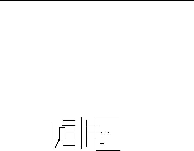
Measuring Pressure
All engine pressure sensors (Figure 8, Item 60) are 3-wire devices. As pressure changes, output changes. The ECU
(Figure 8, Item 57) supplies the sensor with a reference voltage (Figure 8, Item 58) and ground (Figure 8, Item 59).
It monitors the output voltage from the sensor signal input (Figure 8, Item 56). As the pressure changes, it causes
the input to the ECU to change. The ECU compares the input value to a pre-programmed value in the ECU's memory.
60
57
58
I
56
C
59
61
HYEX01682
Figure 8. Typical Pressure Sensor Schematic.
There are many types of devices, and depending on the integrated circuit (Figure 8, Item 61) in the device, the ECU
determines how to process the input signal. If the input value is near the expected value, then the ECU assumes
everything is functioning properly. If the value is above or below the expected value, the ECU will set the appropriate
diagnostic trouble code (DTC).
The barometric air pressure (BAP) sensor is used to determine the pressure of the ambient air at the mounting
location of the ECU. This helps the ECU determine the air density for calculating the correct air/fuel ratio. The BAP
sensor is located within the ECU. This sensor cannot be repaired or replaced without replacing the entire ECU.
The fuel rail pressure sensor sends a pressure equivalent signal to the ECU. The ECU monitors fuel pressure to
control the amount and timing of fuel being transferred from the high-pressure fuel pump to the high-pressure
common rail (HPCR). The ECU uses this signal input to determine if fuel rail pressure is adequate for the current
operating condition. The ECU will command more or less fuel from the high-pressure fuel pump by altering the signal
to the suction control valve. The ECU also uses this sensor to determine if there is an electronic injector (EI) problem
by measuring the drop of pressure every time the engine injects fuel to a specific cylinder. This sensor is used for
engine protection.
The fuel transfer pressure sensor sends a pressure equivalent signal to the ECU. The ECU monitors fuel pressure
to determine if fuel is continuously passing through the low-pressure side of the fuel system, or if there is a leak or
blockage.