
TM 5-3805-294-23-1
0003
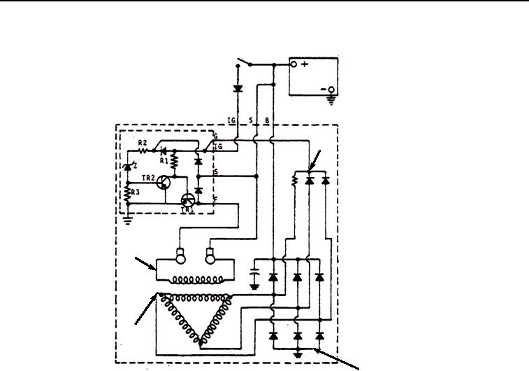
ELECTRICAL SYSTEM - Continued
65
62
63
64
HYEX01683
Figure 9. Typical Alternator Operation.
Starter Motor
NOTE
Never operate starter motor longer than 30 seconds. Allow at least 2 minutes for cooling and
battery recovery before operating again. Overheating caused by excessive operation will
seriously damage starter motor.
The starter motor is part of the starting circuit, the starter motor is used to turn the engine flywheel fast enough to
start the engine. The reduction or R-type starter motor is a positive shift type and consists of the motor, reduction
gear, overrunning clutch, and solenoid switch. The solenoid switch and overrunning clutch mechanism are on the
same axis. In a conventional starter motor, the armature and overrunning pinion rotate at the same speed. In a
reduction-type starter motor, the armature rotation is reduced by one-fourth to one-third by the reduction gears, and
is transmitted to the pinion through the clutch mechanism.
When solenoid assembly (Figure 10, Item 66) engages, it pushes overrunning clutch drive (Figure 10, Item 67) to
engage pinion gear (Figure 10, Item 68) in starter gear on flywheel. As armature (Figure 10, Item 69) turns, it cranks
the engine. When engine starts, overrunning clutch drive (Figure 10, Item 67) spins freely on shaft. This prevents
over-speeding of the armature by the flywheel. When the key switch is released, current to the solenoid hold-in
winding is shut off. Current can feed through both the pull-in and hold-in windings from the main contacts, but the
direction of current is reversed in the pull-in winding. The two windings cancel each other, and the solenoid is
released. A spring pushes the solenoid back to disengaged position. This opens the main contacts and shuts off
current to field windings (Figure 10, Item 70) and armature (Figure 10, Item 69). Overrunning clutch drive (Figure
10, Item 67) retracts, disengaging pinion gear (Figure 10, Item 68) from the flywheel.