
TM 5-3805-294-23-1
0003
HYDRAULIC SYSTEM - Continued
When the dig or swing control lever is returned to neutral, the swing park brake release pilot valve stops the flow of
pilot oil to the swing motor (Figure 11, Item 75). Spring (Figure 11, Item 76) pushes the brake piston (Figure 11, Item
72) down, forcing the oil through orifice (Figure 11, Item 77) into the swing motor case. The orifice prevents the brake
piston from moving quickly and delays the application of the swing park brake until the upper structure is stopped
or nearly stopped. The spring force on the brake piston engages the friction plate (Figure 11, Item 74), which acts
on the cylinder block (Figure 11, Item 78) and the plate (Figure 11, Item 73), which acts on the inside of the swing
motor housing, securing the upper structure from moving.
Swing Motor Make-Up Check Valve
When the swing control lever is returned to the neutral position while the upper structure is in motion, the weight of
the upper structure will continue to turn the swing motor, which causes it to act like a pump. The flow caused by the
pumping action of the swing motor cannot flow through the control valve because the work ports are blocked by the
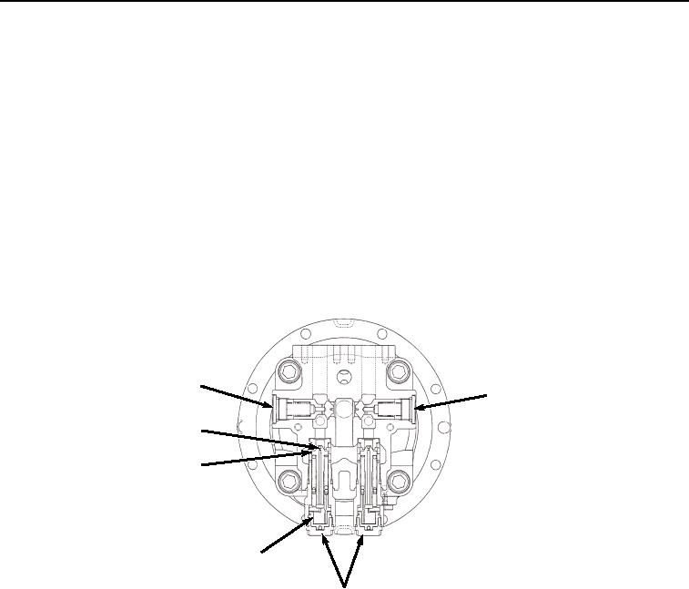
valve spool. The high-pressure oil is forced through the crossover relief valve (Figure 12, Item 79). The make-up
check valve (Figure 12, Item 80) provides oil to the low-pressure side of the swing motor to prevent cavitation.
80
80
83
82
81
79
HYEX01687
Figure 12. Crossover Relief Valve and Make-Up Check Valve Operation.
Swing Motor Crossover Relief Valve
The swing motor crossover relief valves (Figure 12, Item 79) are direct-acting relief valves with a shock reducing
function. The piston (Figure 12, Item 81) allows the spring force on the poppet (Figure 12, Item 82) to be reduced.
Additionally, as oil flows through the orifice (Figure 12, Item 83) and moves the piston, a pressure difference is
created from one side of the poppet to the other. The reduced spring force and the pressure difference on the poppet
allow the poppet to open below set pressure to reduce pressure spikes. As the piston moves, spring force on the
poppet is increased. Once the piston reaches full stroke, the pressure difference is eliminated and the pressure in
the swing circuit will reach set pressure.
Rotary Manifold
The center joint is a 360 rotary manifold (Figure 13, Item 84), located at the base of the boom. It allows return oil
(Figure 13, Item 85), supply oil (Figure 13, Item 86), and pilot oil (Figure 13, Item 87) to flow to and from the travel
motors (Figure 13, Item 88) without twisting hoses when the upper structure is rotated. The inner spindle is connected
to the upper structure and the housing is connected to the undercarriage. The housing rotates about the spindle