
TM 5-3805-294-23-1
0003
POWER TRAIN - Continued
114
115
116
HYEX01692
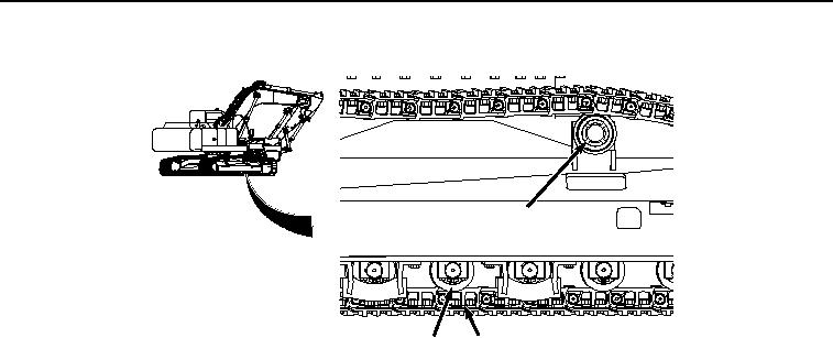
Figure 17.
Track Shoe, Carrier Roller, and Lower Roller.
Travel Motors
The travel motors are located inside the tracks to prevent damage during operation. The travel system has a spring-
applied, hydraulically released parking brake. The parking brake engages as soon as the travel controls are released.
Travel Gearbox
The travel gearbox is a triple-reduction planetary-drive gearbox. The gearbox is interchangeable from the right to
the left side of the machine. The travel motor housing (Figure 18, Item 117), which is fastened to the track frame,
serves as the main support for the drum (Figure 18, Item 118), and planetary gears (ring gear (Figure 18, Item 119),
third stage carrier (Figure 18, Item 120), third stage sun gear (Figure 18, Item 121), second stage carrier (Figure 18,
Item 122), second stage sun gear (Figure 18, Item 123), first stage carrier (Figure 18, Item 124)), first stage sun gear
(input shaft) (Figure 18, Item 125), first stage planet gear (Figure 18, Item 126), second stage planet gear (Figure
18, Item 127), and third stage planet gear (Figure 18, Item 128). The travel motor is connected to and drives the
gearbox through first stage sun gear (input shaft) (Figure 18, Item 125). The third stage carrier (Figure 18, Item 120)
is fixed to the housing. A replaceable thrust pad (Figure 18, Item 129) is used in the gearbox cover to keep the first
stage sun gear (input shaft) (Figure 18, Item 125) in position.