
TM 5-3805-294-23-1
0003
FUEL SYSTEM - Continued
Fuel flows up a passage (Figure 21, Item 150) between the outside of the filter element and the inside of the canister,
and up through the 30-micron particle filter element (Figure 21, Item 151) and out of the holes in the filter element.
From there, fuel exits through the outlet (Figure 21, Item 152) at the filter head.
Air can be bled from this part of the fuel system by loosening the bleed screw (Figure 21, Item 153) in the front of
the filter head.
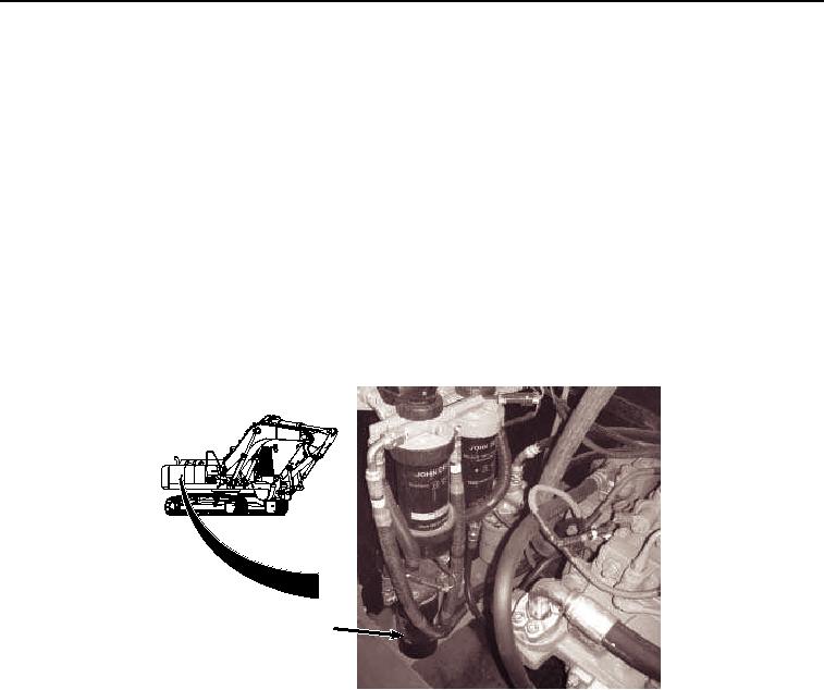
The lubricity filter (Figure 22, Item 132) is designed to add a small amount of an additive to the fuel as the engine
runs. The additive improves the lubricity of the fuel. The lubricity filter looks like a spin on fuel filter. It is a cartridge
that spins. The filter element contains the additive. All the fuel that flows to the engine passes through the lubricity
filter element. The lubricity filter contains an orifice, which all the fuel flows through. The orifice creates a delta
pressure across the device. The pressure rise pushes fuel into the container of additive and pushes additive up the
capillary tube back into the fuel stream. Also there is wax plug at the top of the filter that seals the device from
shipping. The wax plug dissolves on contact with the fuel. It is supposed to take 24 hours to dissolve. The wax plug
contains additive in the top of the lubricity filter that wicks into the fuel during the first 24 hours while the wax plug is
dissolving.
132
HYEX01695
Figure 22.
Lubricity Filter Operation.
Fuel enters the final filter fuel/water separator at inlet (Figure 23, Item 154), flows through filter element (Figure 23,
Item 155), and exits through outlet (Figure 23, Item 156) to the high pressure pump. The 2-micron filter element is
housed in a sediment bowl attached to the filter head with a threaded retaining ring.