
TM 5-3805-294-23-1
0003
FUEL SYSTEM - Continued
141
130
137
133
141
131
140
132
134
135
139
136
138
HYEX01694
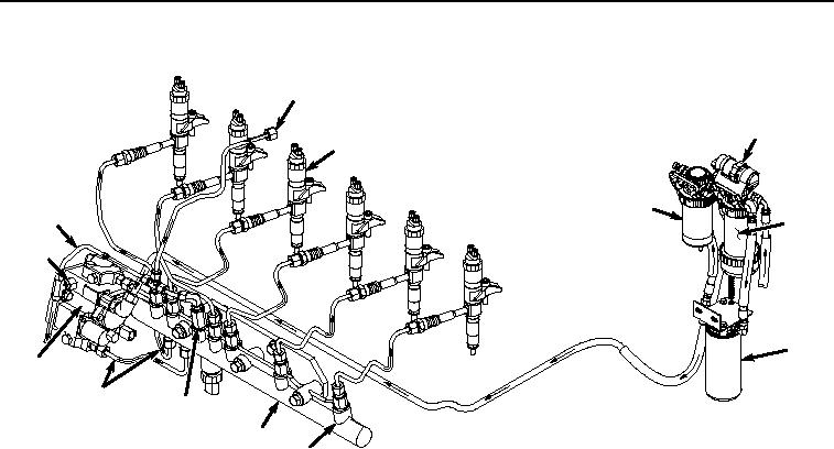
Figure 19.
Fuel System Operation.
This pump is timed consistent with the engine timing to ensure correct fuel delivery amount for optimum cylinder
firing. The high-pressure fuel pump raises fuel pressure to the required amount for injection. This high-pressure fuel
is routed through the pressurized fuel lines (Figure 19, Item 135) and into the high-pressure common rail (Figure 19,
Item 136). The high-pressure common rail evenly distributes fuel to all of the electronic injectors (Figure 19, Item
137) through the flow restrictors (Figure 19, Item 138). Electronic injectors produce measured amounts of fuel into
their respective cylinders to be fired.
If excess fuel pressure develops in the high-pressure common rail, the safety relief valve (Figure 19, Item 139) opens
and bleeds off fuel through the fuel leak-off line back to the tank. Excess fuel in the high-pressure fuel pump exits
the overflow orifice (Figure 19, Item 140) and is routed back to the tank through fuel leak-off line (Figure 19, Item
141).
The ECU sends a signal in specific sequence to each electronic injector. This controls the volume of fuel, the timing
of delivery, and the rate of delivery for each electronic injector. Excess fuel from the nozzle routes through the fuel
return line and back to the fuel tank. The fuel goes through a fuel cooler prior to returning to the fuel tank.
Tank, Strainer, and Drain Valve
The fuel tank (Figure 20, Item 142) has a 132 gal (500 L) capacity and is equipped with a low fuel level alarm and
a vented fill cap (Figure 20, Item 143). The strainer (Figure 20, Item 144) is designed to keep debris from entering
the fuel system. The drain valve is located in the pump compartment and is used to remove water and debris from
the fuel tank.