
TM 5-3805-294-23-1
0003
POWER TRAIN
Power Train Operation
On the HYEX, a solenoid is activated when pressure is sensed at the travel pressure sensor, the swing pressure
sensor is not sensing pressure (no front attachment pressure sensor functions activated), either pump delivery
pressures are low, and either control pressures are high. Activation of the travel speed solenoid sends pilot pressure
to the travel speed change valve in the travel motors. Pressure at the travel speed change valve changes the
displacement of the travel motors allowing for fast travel speed. Since either delivery pressure may be low and either
control pressure may be high, the travel motor will shift speeds even if the other motor is stationary. If the machine
is travelling in fast travel speed and a dig or swing function is operated, the machine will remain in fast travel speed,
but will slow in travel speed as hydraulic oil is routed to other functions.
Tracks/Adjuster/Rollers
The track assembly consists of the chain and shoes. The travel motor drives the track to move the HYEX.
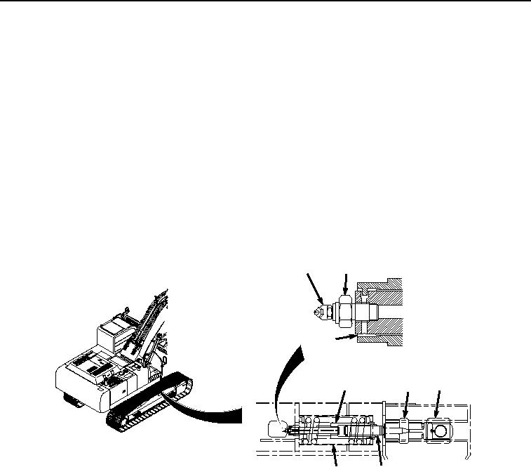
The track adjuster and recoil spring (Figure 16, Item 106) are supported by the track frame. Shock loads on the track
and front idler (Figure 16, Item 107) are absorbed by the recoil spring.
112
109
113
108
111
107
106
110
HYEX01691
Figure 16.
Track Adjuster and Recoil Spring Assembly Operation.
To decrease track sag, pump grease into cylinder (Figure 16, Item 108) through grease fitting (Figure 16, Item 109).
The grease pushes the piston (Figure 16, Item 110) against the yoke (Figure 16, Item 111), moving the front idler
(Figure 16, Item 107) out, and reducing track sag. The grease fitting (Figure 16, Item 109) is protected from excess
pressure by a check ball. Increasing track sag is accomplished by loosening the nut (Figure 16, Item 112) to release
grease from the cylinder (Figure 16, Item 108) through the concealed grease relief passage (Figure 16, Item 113).
When releasing grease from the cylinder, only loosen the nut (Figure 16, Item 112).
The HYEX has two carrier rollers (Figure 17, Item 114) and nine lower track rollers (Figure 17, Item 115) on each
side of the machine. The rollers guide the tracks (Figure 17, Item 116) and keep the tracks in contact with the ground.